Toyota Avalon (XX50): Rear Upper Arm
Components
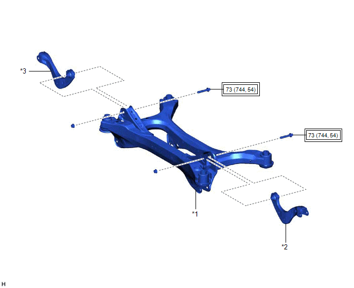
COMPONENTS
ILLUSTRATION
|
*1 | REAR SUSPENSION MEMBER SUB-ASSEMBLY |
*2 | REAR UPPER CONTROL ARM ASSEMBLY LH |
|
*3 | REAR UPPER CONTROL ARM ASSEMBLY RH |
- | - |
 |
Tightening torque for "Major areas involving basic vehicle performance such as moving/turning/stopping": N*m (kgf*cm, ft.*lbf) |
- | - |
Installation
INSTALLATION
PROCEDURE
1. INSTALL REAR UPPER CONTROL ARM ASSEMBLY LH
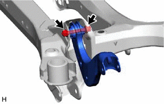
| (a) Temporarily install the rear upper control arm assembly LH to the rear suspension member sub-assembly with the bolt and nut.
NOTICE:
- Because the nut has its own stopper, do not turn the nut. Tighten the bolt with the nut secured.
- Insert the bolt with the threaded end facing the front of the vehicle.
| |
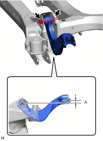
(b) Position the rear upper control arm assembly LH as shown in the illustration.
Reference Length (A):
1.2 mm (0.0472 in.)
(c) Fully tighten the bolt.
Torque:
73 N·m {744 kgf·cm, 54 ft·lbf}
NOTICE:
Because the nut has its own stopper, do not turn the nut. Tighten the bolt with the nut secured.
2. INSTALL REAR UPPER CONTROL ARM ASSEMBLY RH
HINT:
Perform the same procedure as for the LH side.
3. INSTALL REAR SUSPENSION MEMBER SUB-ASSEMBLY
Click here

Removal
REMOVAL
CAUTION / NOTICE / HINT
The
necessary procedures (adjustment, calibration, initialization, or
registration) that must be performed after parts are removed and
installed, or replaced during rear upper control arm assembly
removal/installation are shown below.
Necessary Procedures After Parts Removed/Installed/Replaced (for Gasoline Model:) |
Replaced Part or Performed Procedure |
Necessary Procedure | Effect/Inoperative Function when Necessary Procedure not Performed |
Link |
| Rear wheel alignment adjustment |
Perform system variant learning and acceleration sensor zero point calibration. |
- VSC disabled or malfunctioning
- DTCs are output
- Slip indicator light illuminated
- ABS warning light illuminated
|
 |
|
Suspension, tires, etc. (The vehicle height changes because of suspension or tire replacement.) |
- Measure ultrasonic sensor detection angle
- Ultrasonic sensor detection angle registration
|
- Intelligent Clearance Sonar System
- Intuitive Parking Assist System
|
|
|
Rear television camera assembly optical axis adjustment (Back camera position setting) |
Parking Assist Monitor System |
for Initialization
for Calibration |
- Parking assist ECU initialization
- Adjust steering angle
- Television camera assembly optical axis adjustment (Back camera position setting)
| Panoramic View Monitor System |
for Initialization
for Calibration |
|
Gas leak from exhaust system is repaired |
Inspection After Repair |
- Poor idle, etc.
- Engine start function, etc.
|
|
Necessary Procedures After Parts Removed/Installed/Replaced (for HV Model:) |
Replaced Part or Performed Procedure |
Necessary Procedure | Effect/Inoperative Function when Necessary Procedure not Performed |
Link |
| Rear wheel alignment adjustment |
- Clear zero point calibration data.
- Perform yaw rate and acceleration sensor zero point calibration.
|
- DTCs are stored
- ABS warning light illuminates
- Brake warning light / yellow (minor malfunction) illuminates
- Slip indicator light illuminates
- VSC disabled or malfunctions
|
|
|
Suspension, tires, etc. (The vehicle height changes because of suspension or tire replacement.) |
- Measure ultrasonic sensor detection angle
- Ultrasonic sensor detection angle registration
|
- Intelligent Clearance Sonar System
- Intuitive Parking Assist System
|
|
|
Rear television camera assembly optical axis adjustment (Back camera position setting) |
Parking Assist Monitor System |
for Initialization
for Calibration |
- Parking assist ECU initialization
- Adjust steering angle
- Television camera assembly optical axis adjustment (Back camera position setting)
| Panoramic View Monitor System |
for Initialization
for Calibration |
|
Gas leak from exhaust system is repaired |
Inspection After Repair |
- Poor idle, etc.
- Engine start function, etc.
|
|
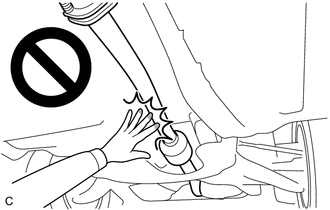
CAUTION:
To prevent burns, do not touch the engine, exhaust pipe or other high temperature components while the engine is hot.
PROCEDURE
1. REMOVE REAR SUSPENSION MEMBER SUB-ASSEMBLY
Click here
2. REMOVE REAR UPPER CONTROL ARM ASSEMBLY LH
| (a) Remove the bolt, nut and rear upper control arm assembly LH from the rear suspension member sub-assembly.
NOTICE: Because the nut has its own stopper, do not turn the nut. Loosen the bolt with the nut secured. |
|
3. REMOVE REAR UPPER CONTROL ARM ASSEMBLY RH
HINT:
Perform the same procedure as for the LH side.