Installation
INSTALLATION
CAUTION / NOTICE / HINT
HINT:
- Use the same procedure for the RH side and LH side.
- The following procedure is for the LH side.
PROCEDURE
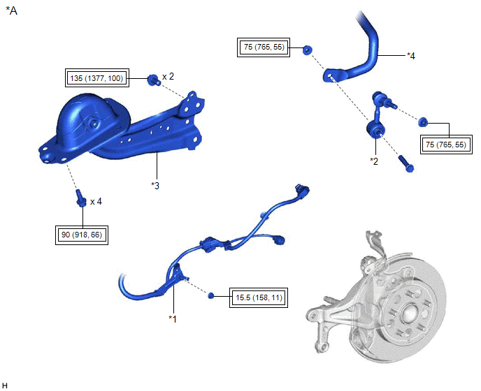
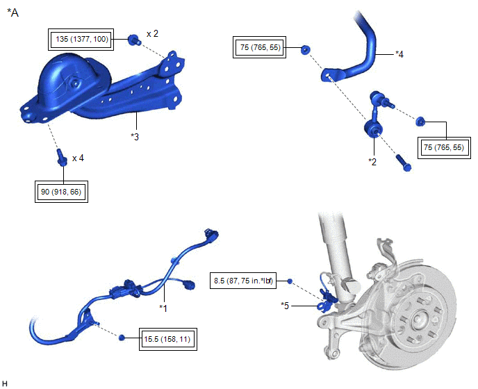
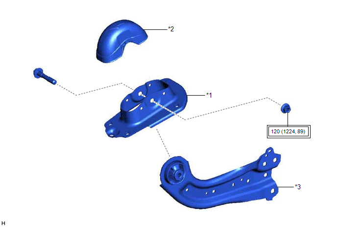
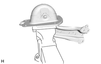
1. INSTALL REAR SUSPENSION ARM BRACKET
| (a) Temporarily install the rear suspension arm bracket to the rear trailing arm assembly with the bolt and nut.
NOTICE:
- Because the bolt has its own stopper, do not turn the bolt. Tighten the nut with the bolt secured.
- Insert the bolt from the inside of the vehicle.
| |
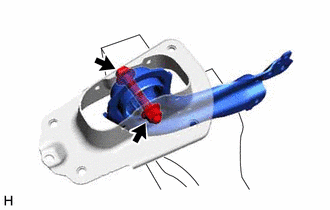
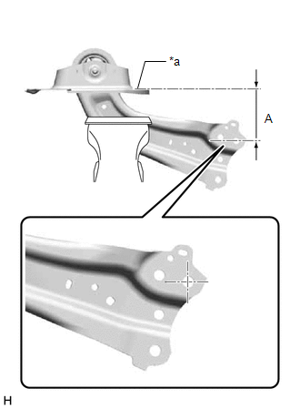
| (b) Position the rear trailing arm assembly as shown in the illustration.
Reference Length (A): 120 mm (4.72 in.) |
 |
|
*a | Upper Surface of Rear Suspension Arm Bracket | | |
(c) Fully tighten the nut.
Torque:
120 N·m {1224 kgf·cm, 89 ft·lbf}
NOTICE:
Because the bolt has its own stopper, do not turn the bolt. Tighten the nut with the bolt secured.
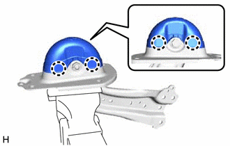
2. INSTALL REAR SUSPENSION ARM COVER
(a) Engage the 4 claws and install the rear suspension arm cover.
3. INSTALL REAR TRAILING ARM ASSEMBLY
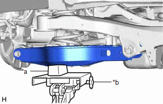
(a) Using a transmission jack and a wooden block, support the rear No. 2 suspension arm assembly.
NOTICE:
- When jacking up the rear No. 2 suspension arm assembly, be sure to jack it up slowly.
- Make sure to perform this operation with the vehicle kept as low as possible.
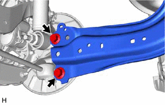
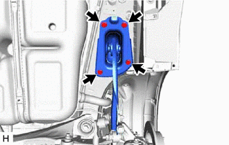
(b) Install the rear trailing arm assembly to the vehicle with the 4 bolts.
Torque:
90 N·m {918 kgf·cm, 66 ft·lbf}
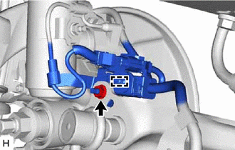
(c) Install the rear trailing arm assembly to the rear axle carrier sub-assembly with the 2 bolts.
Torque:
135 N·m {1377 kgf·cm, 100 ft·lbf}
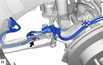
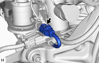
4. INSTALL NO. 2 PARKING BRAKE WIRE ASSEMBLY (w/o AVS)
| (a) Install the No. 2 parking brake wire assembly to the rear trailing arm assembly with the nut.
Torque: 15.5 N·m {158 kgf·cm, 11 ft·lbf} | |
(b) Engage the 2 clamps.
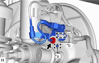
5. INSTALL NO. 2 PARKING BRAKE WIRE ASSEMBLY (w/ AVS)
| (a) Install the No. 2 parking brake wire assembly to the rear trailing arm assembly with the nut.
Torque: 15.5 N·m {158 kgf·cm, 11 ft·lbf} | |
(b) Engage the clamp.
|
(c) Engage the guide and install the wire harness bracket. | |
(d) Install the nut.
Torque:
8.5 N·m {87 kgf·cm, 75 in·lbf}
(e) Engage the clamp and install the No. 2 parking brake wire assembly to the wire harness bracket.
| (f) Connect the connector. | |
6. INSTALL REAR STABILIZER LINK ASSEMBLY
Click here

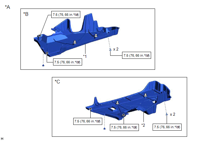
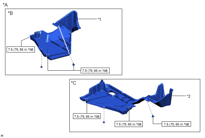
7. INSTALL NO. 1 FLOOR UNDER COVER (for HV Model)
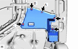
| (a) for RH Side: (1) Install the No. 1 floor under cover with the 2 grommets (B).
Torque: Grommet (B) : 7.5 N·m {76 kgf·cm, 66 in·lbf}
(2) Install the bolt and clip (A). Torque: Bolt : 7.5 N·m {76 kgf·cm, 66 in·lbf} |
|
8. INSTALL NO. 2 FLOOR UNDER COVER (for HV Model)
| (a) for LH Side: (1) Install the No. 2 floor under cover with the 2 grommets (B) and clip (C).
Torque: Grommet (B) : 7.5 N·m {76 kgf·cm, 66 in·lbf}
(2) Install the bolt and clip (A). Torque: Bolt : 7.5 N·m {76 kgf·cm, 66 in·lbf} |
|
9. INSTALL NO. 1 FLOOR UNDER COVER (for Gasoline Model)
(a) for RH Side:
Click here
10. INSTALL NO. 2 FLOOR UNDER COVER (for Gasoline Model)
(a) for LH Side:
Click here
11. INSTALL REAR WHEEL
Click here
12. INSPECT AND ADJUST REAR WHEEL ALIGNMENT
Click here
13. PERFORM INITIALIZATION
for Gasoline Model:
- Intelligent Clearance Sonar System
- Intuitive Parking Assist System
|
|
|
Parking Assist Monitor System |
for Initialization
for Calibration |
|
Panoramic View Monitor System |
for Initialization
for Calibration |
for HV Model:
- Intelligent Clearance Sonar System
- Intuitive Parking Assist System
|
|
|
Parking Assist Monitor System |
for Initialization
for Calibration |
|
Panoramic View Monitor System |
for Initialization
for Calibration |
Removal
REMOVAL
CAUTION / NOTICE / HINT
The
necessary procedures (adjustment, calibration, initialization, or
registration) that must be performed after parts are removed and
installed, or replaced during rear trailing arm assembly
removal/installation are shown below.
Necessary Procedures After Parts Removed/Installed/Replaced (for Gasoline Model:) |
Replaced Part or Performed Procedure |
Necessary Procedure | Effect/Inoperative Function when Necessary Procedure not Performed |
Link |
| Rear wheel alignment adjustment |
Perform system variant learning and acceleration sensor zero point calibration. |
- VSC disabled or malfunctioning
- DTCs are output
- Slip indicator light illuminated
- ABS warning light illuminated
|
 |
|
Suspension, tires, etc. (The vehicle height changes because of suspension or tire replacement.) |
- Measure ultrasonic sensor detection angle
- Ultrasonic sensor detection angle registration
|
- Intelligent Clearance Sonar System
- Intuitive Parking Assist System
|
|
|
Rear television camera assembly optical axis adjustment (Back camera position setting) |
Parking Assist Monitor System |
for Initialization
for Calibration |
- Parking assist ECU initialization
- Adjust steering angle
- Television camera assembly optical axis adjustment (Back camera position setting)
| Panoramic View Monitor System |
for Initialization
for Calibration |
Necessary Procedures After Parts Removed/Installed/Replaced (for HV Model:) |
Replaced Part or Performed Procedure |
Necessary Procedure | Effect/Inoperative Function when Necessary Procedure not Performed |
Link |
| Rear wheel alignment adjustment |
- Clear zero point calibration data.
- Perform yaw rate and acceleration sensor zero point calibration.
|
- DTCs are stored
- ABS warning light illuminates
- Brake warning light / yellow (minor malfunction) illuminates
- Slip indicator light illuminates
- VSC disabled or malfunctions
|
|
|
Suspension, tires, etc. (The vehicle height changes because of suspension or tire replacement.) |
- Measure ultrasonic sensor detection angle
- Ultrasonic sensor detection angle registration
|
- Intelligent Clearance Sonar System
- Intuitive Parking Assist System
|
|
|
Rear television camera assembly optical axis adjustment (Back camera position setting) |
Parking Assist Monitor System |
for Initialization
for Calibration |
- Parking assist ECU initialization
- Adjust steering angle
- Television camera assembly optical axis adjustment (Back camera position setting)
| Panoramic View Monitor System |
for Initialization
for Calibration |
HINT:
- Use the same procedure for the RH side and LH side.
- The following procedure is for the LH side.
PROCEDURE
1. REMOVE REAR WHEEL
Click here
2. REMOVE NO. 2 FLOOR UNDER COVER (for Gasoline Model)
(a) for LH Side:
Click here
3. REMOVE NO. 1 FLOOR UNDER COVER (for Gasoline Model)
(a) for RH Side:
Click here
4. REMOVE NO. 2 FLOOR UNDER COVER (for HV Model)
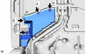
| (a) for LH Side: (1) Remove the bolt and clip (A). (2) Disengage the 2 grommets (B) and clip (C) to remove the No. 2 floor under cover. |
|
5. REMOVE NO. 1 FLOOR UNDER COVER (for HV Model)
| (a) for RH Side: (1) Remove the bolt and clip (A). (2) Disengage the 2 grommets (B) to remove the No. 1 floor under cover. |
|
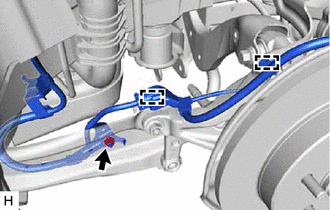
6. SEPARATE NO. 2 PARKING BRAKE WIRE ASSEMBLY (w/o AVS)
| (a) Disengage the 2 clamps. | |
(b) Remove the nut and separate the No. 2 parking brake wire assembly from the rear trailing arm assembly.
7. SEPARATE NO. 2 PARKING BRAKE WIRE ASSEMBLY (w/ AVS)
| (a) Disconnect the connector. | |
| (b) Remove the nut and disengage the clamp. | |
(d) Remove the nut and separate the No. 2 parking brake wire assembly from the rear trailing arm assembly.
8. REMOVE REAR STABILIZER LINK ASSEMBLY
Click here
9. REMOVE REAR TRAILING ARM ASSEMBLY
| (a) Using a transmission jack and a wooden block, support the rear No. 2 suspension arm assembly.
NOTICE:
- When jacking up the rear No. 2 suspension arm assembly, be sure to jack it up slowly.
- Make sure to perform this operation with the vehicle kept as low as possible.
|
 |
|
*a | Wooden Block | |
*b | Transmission Jack | | |
| (b) Remove the 2 bolts and separate the rear trailing arm assembly from the rear axle carrier sub-assembly. |
|
| (c) Remove the 4 bolts and rear trailing arm assembly. |
|
10. REMOVE REAR SUSPENSION ARM COVER
| (a) Secure the rear trailing arm assembly in a vise using aluminum plates.
NOTICE: Do not overtighten the vise. | |
| (b) Disengage the 4 claws and remove the rear suspension arm cover. |
|
11. REMOVE REAR SUSPENSION ARM BRACKET
| (a) Remove the bolt, nut and rear suspension arm bracket from the rear trailing arm assembly.
NOTICE: Because the bolt has its own stopper, do not turn the bolt. Loosen the nut with the bolt secured. |
|