Installation
INSTALLATION
PROCEDURE
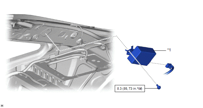
1. INSTALL TIRE PRESSURE WARNING ECU AND RECEIVER
NOTICE:
- Do not drop the tire pressure warning ECU and receiver, strike it with tools or subject it to impact.
- If the tire pressure warning ECU and receiver is subjected to an impact, replace it with a new one.
(a) Connect the connector.
(b) Engage the 2 guides and install the tire pressure warning ECU and receiver with the bolt.
Torque:
8.3 N·m {85 kgf·cm, 73 in·lbf}
2. INSTALL ROOF SIDE INNER GARNISH RH
Click here 
3. REGISTER TRANSMITTER ID
for HV Model: Click here
for Gasoline Model: Click here
4. INSPECT TIRE PRESSURE WARNING SYSTEM
for HV Model: Click here
for Gasoline Model: Click here
5. PERFORM INITIALIZATION
for HV Model: Click here
for Gasoline Model: Click here
6. PERFORM DIAGNOSTIC SYSTEM CHECK
for HV Model: Click here
for Gasoline Model: Click here
7. INSPECT SRS WARNING LIGHT
for HV Model: Click here
for Gasoline Model: Click here
Removal
REMOVAL
CAUTION / NOTICE / HINT
The
necessary procedures (adjustment, calibration, initialization or
registration) that must be performed after parts are removed and
installed, or replaced during tire pressure warning ECU and receiver
removal/installation are shown below.
Necessary Procedures After Parts Removed/Installed/Replaced (for Gasoline Model) |
Replacement Part or Procedure |
Necessary Procedures | Effects/Inoperative when not Performed |
Link |
|
*: When performing learning using the Techstream.
Click here  |
|
Disconnect cable from battery terminal |
Perform steering sensor zero point calibration |
Lane Departure Alert System (w/ Steering Control) |
|
|
Pre-collision System |
|
Intelligent Clearance Sonar System* |
|
Lighting System (for Gasoline Model with Cornering Light) |
|
Memorize steering angle neutral point |
Parking Assist Monitor System |
|
|
Panoramic View Monitor System |
|
|
Tire pressure warning ECU and receiver |
- Register transmitter ID
- Initialize tire pressure warning system
|
- When DTC detection conditions of "transmitter ID not received" DTC are
met, TPWS indicator blinks for 1 minute, and then illuminates
- Tire pressure warning function
|
for Registration
for Initialization |
Necessary Procedures After Parts Removed/Installed/Replaced (for HV Model) |
Replacement Part or Procedure |
Necessary Procedures | Effects/Inoperative when not Performed |
Link |
|
*: When performing learning using the Techstream.
Click here |
|
Disconnect cable from negative auxiliary battery terminal |
Perform steering sensor zero point calibration |
Lane Departure Alert System (w/ Steering Control) |
|
|
Pre-collision System |
|
Intelligent Clearance Sonar System* |
|
Lighting System (for HV Model with Cornering Light) |
|
Memorize steering angle neutral point |
Parking Assist Monitor System |
|
|
Panoramic View Monitor System |
|
|
Tire pressure warning ECU and receiver |
- Register transmitter ID
- Initialize tire pressure warning system
|
- When DTC detection conditions of "transmitter ID not received" DTC are
met, TPWS indicator blinks for 1 minute, and then illuminates
- Tire pressure warning function
| for Registration
for Initialization
|
CAUTION:
Some
of these service operations affect the SRS airbag system. Read the
precautionary notices concerning the SRS airbag system before servicing.
for Gasoline Model: Click here
for HV Model: Click here
NOTICE:
When
replacing the tire pressure warning ECU and receiver, read the
transmitter IDs stored in the old ECU using the Techstream and write
them down before removal.
for HV Model: Click here
for Gasoline Model: Click here
PROCEDURE
1. PRECAUTION
NOTICE:
After
turning the engine switch (for Gasoline Model) or power switch (for HV
Model) off, waiting time may be required before disconnecting the cable
from the negative (-) auxiliary battery terminal. Therefore, make sure
to read the disconnecting the cable from the negative (-) auxiliary
battery terminal notices before proceeding with work.
Click here
2. REMOVE ROOF SIDE INNER GARNISH RH
Click here
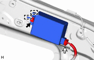
3. REMOVE TIRE PRESSURE WARNING ECU AND RECEIVER
NOTICE:
- Do not drop the tire pressure warning ECU and receiver, strike it with tools or subject it to impact.
- If the tire pressure warning ECU and receiver is subjected to an impact, replace it with a new one.
(b) Disengage the 2 guides.
(c) Disconnect the connector to remove the tire pressure warning ECU and receiver.