Installation
INSTALLATION
PROCEDURE
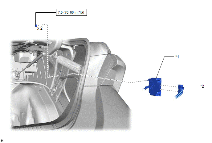
1. INSTALL ABSORBER CONTROL ECU
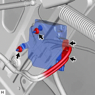
(a) Install the absorber control ECU with the 2 nuts.
Torque:
7.5 N·m {76 kgf·cm, 66 in·lbf}
NOTICE:
- Avoid any impact to the absorber control ECU.
- Do not drop the absorber control ECU. If it is dropped, replace it with a new one.
(b) Connect the 2 connectors to the absorber control ECU.
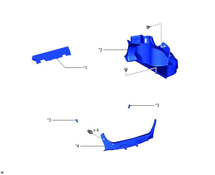
2. INSTALL LUGGAGE COMPARTMENT TRIM INNER COVER RH
Click here 
3. INSTALL LUGGAGE COMPARTMENT INNER TRIM PAD
Click here
4. INSTALL REAR FLOOR FINISH PLATE
Click here
5. INSTALL NO. 1 LUGGAGE COMPARTMENT TRIM HOOK
Click here
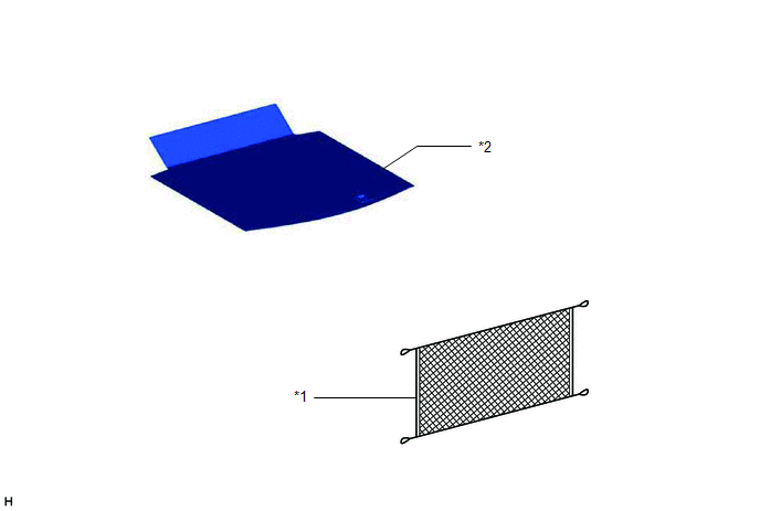
6. INSTALL BAGGAGE HOLDER NET
Click here
7. INSTALL SPARE WHEEL COVER ASSEMBLY
Click here
8. CONNECT CABLE TO NEGATIVE BATTERY TERMINAL
Click here
NOTICE:
When disconnecting the cable, some systems need to be initialized after the cable is reconnected.
Click here
9. PERFORM TEST MODE PROCEDURE
NOTICE:
After
replacing the absorber control ECU, it is necessary to perform
registration of vehicle identification information. Vehicle
identification information is automatically acquired when the system
enters test mode.
Click here
Removal
REMOVAL
CAUTION / NOTICE / HINT
The
necessary procedures (adjustment, calibration, initialization or
registration) that must be performed after parts are removed and
installed, or replaced during absorber control ECU removal/installation
are shown below.
Necessary Procedures After Parts Removed/Installed/Replaced |
Replaced Part or Performed Procedure |
Necessary Procedure | Effect/Inoperative Function when Necessary Procedure not Performed |
Link |
|
*: When performing learning using the Techstream.
Click here  |
|
Replacement of the absorber control ECU |
Registration of vehicle identification information |
- Interrupts damping force control
- DTCs are stored
|
|
|
Disconnect cable from negative battery terminal |
Perform steering sensor zero point calibration |
Lane departure alert system (w/ Steering Control) |
|
|
Pre-collision system |
|
Intelligent clearance sonar system* |
|
Lighting system (for Gasoline Model with Cornering Light) |
|
Memorize steering angle neutral point |
Parking assist monitor system |
|
|
Panoramic view monitor system |
|
PROCEDURE
1. PRECAUTION
NOTICE:
After
turning the engine switch off, waiting time may be required before
disconnecting the cable from the negative (-) battery terminal.
Therefore, make sure to read the disconnecting the cable from the
negative (-) battery terminal notices before proceeding with work.
Click here
2. DISCONNECT CABLE FROM NEGATIVE BATTERY TERMINAL
Click here
NOTICE:
When disconnecting the cable, some systems need to be initialized after the cable is reconnected.
Click here
3. REMOVE SPARE WHEEL COVER ASSEMBLY
Click here
4. REMOVE BAGGAGE HOLDER NET
Click here
5. REMOVE NO. 1 LUGGAGE COMPARTMENT TRIM HOOK
Click here
6. REMOVE REAR FLOOR FINISH PLATE
Click here
7. REMOVE LUGGAGE COMPARTMENT INNER TRIM PAD
Click here
8. REMOVE LUGGAGE COMPARTMENT TRIM INNER COVER RH
Click here
9. REMOVE ABSORBER CONTROL ECU
| (a) Disconnect the 2 connectors from the absorber control ECU. |
|
(b) Remove the 2 nuts and absorber control ECU.
NOTICE:
- Avoid any impact to the absorber control ECU.
- Do not drop the absorber control ECU. If it is dropped, replace it with a new one.