Components
COMPONENTS
ILLUSTRATION
|
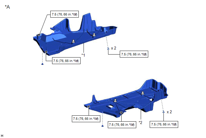
*A | for Gasoline Model |
- | - |
|
*1 | NO. 1 FLOOR UNDER COVER |
*2 | NO. 2 FLOOR UNDER COVER |
 |
N*m (kgf*cm, ft.*lbf): Specified torque |
- | - |
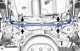
ILLUSTRATION
|
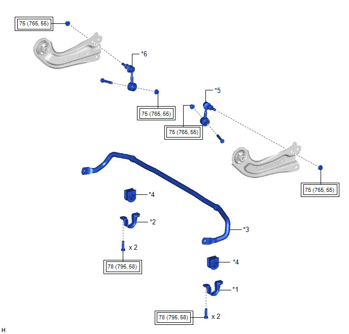
*1 | REAR NO. 1 STABILIZER BAR BRACKET LH |
*2 | REAR NO. 1 STABILIZER BAR BRACKET RH |
|
*3 | REAR STABILIZER BAR |
*4 | REAR STABILIZER BUSHING |
|
*5 | REAR STABILIZER LINK ASSEMBLY LH |
*6 | REAR STABILIZER LINK ASSEMBLY RH |
 |
Tightening torque for "Major areas involving basic vehicle performance such as moving/turning/stopping": N*m (kgf*cm, ft.*lbf) |
- | - |
Inspection
INSPECTION
PROCEDURE
1. INSPECT REAR STABILIZER LINK ASSEMBLY
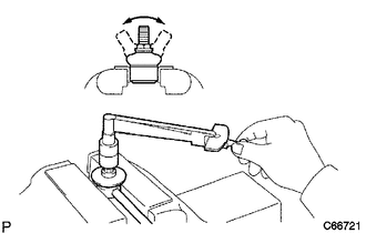
(a) Inspect the turning torque of the ball joint.
(1) Secure the rear stabilizer link assembly in a vise using aluminum plates.
NOTICE:
Do not overtighten the vise.
(2) Install the nut to the rear stabilizer link assembly stud.
(3)
Move the stud back and forth several times. Using a torque wrench, turn
the stud continuously at a rate of 3 to 5 seconds per turn and take the
torque reading on the 5th turn.
Standard Turning Torque:
0.05 to 1.96 N*m (0.6 to 19 kgf*cm, 0.5 to 17 in.*lbf)
HINT:
If the turning torque is not within the specified range, replace the rear stabilizer link assembly with a new one.
(4) Turn the stud to check that the stud does not catch and there is no play.
HINT:
If the stud catches or there is play while turning, replace the rear stabilizer link assembly with a new one.
(b) Inspect the dust cover.
(1) Check that the dust cover is not cracked and that there is no grease on it.
HINT:
If the dust cover is cracked or there is grease on it, replace the rear stabilizer link assembly with a new one.
Installation
INSTALLATION
PROCEDURE
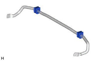
1. INSTALL REAR STABILIZER BUSHING
(a) Install the 2 rear stabilizer bushings to the rear stabilizer bar.
NOTICE:
Be sure to install the rear stabilizer bushings so that each cutout faces the front of the vehicle.
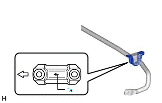
2. INSTALL REAR NO. 1 STABILIZER BAR BRACKET LH
(a) Install the rear No. 1 stabilizer bar bracket LH to the rear stabilizer bushing.
NOTICE:
Be sure to install the rear No. 1 stabilizer bar bracket LH so that each arrow mark faces the front of the vehicle.
|
*a | Arrow Mark |
 |
Front of the Vehicle |
3. INSTALL REAR NO. 1 STABILIZER BAR BRACKET RH
HINT:
Perform the same procedure as for the LH side.
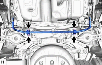
4. INSTALL REAR STABILIZER BAR
| (a)
Install the rear stabilizer bar, rear No. 1 stabilizer bar bracket LH,
rear No. 1 stabilizer bar bracket RH and 2 rear stabilizer bushings to
the rear suspension member sub-assembly with the 4 bolts. Torque:
78 N·m {795 kgf·cm, 58 ft·lbf}
NOTICE:
- Ensure that the identification mark faces the right side of the vehicle.
- Temporarily tighten the bolt (A) and then fully tighten the 2 bolts in the order of (B) and (A).
| |
5. STABILIZE SUSPENSION
Click here 
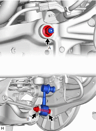
6. INSTALL REAR STABILIZER LINK ASSEMBLY LH
| (a) Install the rear stabilizer link assembly LH with the nut (A).
Torque: 75 N·m {765 kgf·cm, 55 ft·lbf} HINT: If the ball joint turns together with the nut, use a 6 mm hexagon socket wrench to hold the stud bolt. |
|
(b) Install the rear stabilizer link assembly LH with the bolt and nut (B).
Torque:
75 N·m {765 kgf·cm, 55 ft·lbf}
NOTICE:
Because the bolt has its own stopper, do not turn the bolt. Tighten the nut with the bolt secured.
7. INSTALL REAR STABILIZER LINK ASSEMBLY RH
HINT:
Perform the same procedure as for the LH side.
8. INSTALL CENTER EXHAUST PIPE ASSEMBLY
for 2GR-FKS: Click here
for A25A-FXS: Click here
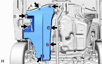
9. INSTALL NO. 1 FLOOR UNDER COVER (for Gasoline Model)
| (a) Install the No. 1 floor under cover with the 2 grommets (B) and 2 clips (C).
Torque: Grommet (B) : 7.5 N·m {76 kgf·cm, 66 in·lbf} |
|
(b) Install the 2 bolts and clip (A).
Torque:
Bolt :
7.5 N·m {76 kgf·cm, 66 in·lbf}
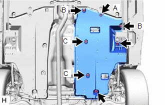
10. INSTALL NO. 2 FLOOR UNDER COVER (for Gasoline Model)
| (a) Install the No. 2 floor under cover with the 2 grommets (B) and 2 clips (C).
Torque: Grommet (B) : 7.5 N·m {76 kgf·cm, 66 in·lbf} |
|
(b) Install the 2 bolts and clip (A).
Torque:
Bolt :
7.5 N·m {76 kgf·cm, 66 in·lbf}
11. INSTALL REAR WHEEL
Click here
12. INSPECT FOR EXHAUST GAS LEAK
for 2GR-FKS: Click here
for A25A-FXS: Click here
Removal
REMOVAL
CAUTION / NOTICE / HINT
The
necessary procedures (adjustment, calibration, initialization, or
registration) that must be performed after parts are removed and
installed, or replaced during rear stabilizer bar removal/installation
are shown below.
Necessary Procedures After Parts Removed/Installed/Replaced (for Gasoline Model:) |
Replaced Part or Performed Procedure |
Necessary Procedure | Effect/Inoperative Function when Necessary Procedure not Performed |
Link |
| Gas leak from exhaust system is repaired |
Inspection After Repair |
- Poor idle, etc.
- Engine start function, etc.
|
 |
Necessary Procedures After Parts Removed/Installed/Replaced (for HV Model:) |
Replaced Part or Performed Procedure |
Necessary Procedure | Effect/Inoperative Function when Necessary Procedure not Performed |
Link |
| Gas leak from exhaust system is repaired |
Inspection After Repair |
- Poor idle, etc.
- Engine start function, etc.
|
|
CAUTION:
To prevent burns, do not touch the engine, exhaust pipe or other high temperature components while the engine is hot.
PROCEDURE
1. REMOVE REAR WHEEL
Click here
2. REMOVE NO. 2 FLOOR UNDER COVER (for Gasoline Model)
| (a) Remove the 2 bolts and clip (A). | |
(b) Disengage the 2 grommets (B) and 2 clips (C) to remove the No. 2 floor under cover.
3. REMOVE NO. 1 FLOOR UNDER COVER (for Gasoline Model)
| (a) Remove the 2 bolts and clip (A). | |
(b) Disengage the 2 grommets (B) and 2 clips (C) to remove the No. 1 floor under cover.
4. REMOVE CENTER EXHAUST PIPE ASSEMBLY
for 2GR-FKS: Click here
for A25A-FXS: Click here
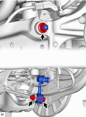
5. REMOVE REAR STABILIZER LINK ASSEMBLY LH
| (a) Loosen the nut (A) of the rear stabilizer link assembly LH.
HINT: If the ball joint turns together with the nut, use a 6 mm hexagon socket wrench to hold the stud bolt. |
|
(b) Loosen the nut (B) of the rear stabilizer link assembly LH.
NOTICE:
Because the bolt has its own stopper, do not turn the bolt. Loosen the nut with the bolt secured.
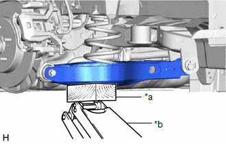
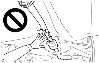
| (c) Using a jack and wooden block, support the rear No. 2 suspension arm assembly.
NOTICE:
- When jacking up the rear No. 2 suspension arm assembly, be sure to jack it up slowly.
- Make sure to perform this operation with the vehicle kept as low as possible.
| |
| (d) Remove the bolt, 2 nuts and rear stabilizer link assembly LH. |
|
6. REMOVE REAR STABILIZER LINK ASSEMBLY RH
HINT:
Perform the same procedure as for the LH side.
7. REMOVE REAR STABILIZER BAR
| (a)
Remove the 4 bolts, rear stabilizer bar, rear No. 1 stabilizer bar
bracket LH, rear No. 1 stabilizer bar bracket RH and 2 rear stabilizer
bushings from the rear suspension member sub-assembly. | |
8. REMOVE REAR NO. 1 STABILIZER BAR BRACKET LH
(a) Remove the rear No. 1 stabilizer bar bracket LH from the rear stabilizer bushing.
9. REMOVE REAR NO. 1 STABILIZER BAR BRACKET RH
HINT:
Perform the same procedure as for the LH side.
10. REMOVE REAR STABILIZER BUSHING
| (a) Remove the 2 rear stabilizer bushings from the rear stabilizer bar. |
|